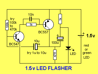
The next circuit flashes a LED and uses a 1.5v supply. The LED does not turn on via the 1k resistor because the characteristic voltage of a LED is between 1.7v and 2.3v, (depending on the colour). It turns on when the 100u is "jacked up" by the collector of the BC557.
The circuit is a charge-pump design. This is where a capacitor (electrolytic) is allowed to charge and is then raised higher and allowed to discharge into a load. The load sees a voltage that can be higher than the supply.
The two transistors operate as a high-gain amplifier with the output being the 47R. The cycle starts with the first transistor being turned on via the 100k. This action also charges the 10u until 0.75v appears on the base of the transistor.
This turns on the second transistor and the negative end of the 10u is raised when the BC557 turns on. This raises the positive end of the 10u and the first transistor turns on even more. This action continues until the first transistor is fully turned on and the BC557 is fully turned on. The voltage across the collector-emitter terminals of the BC557 will be small and about 1v will appear across the 47R. This voltage "jacks up" the 100u and since it is fully charged via the 1k resistor, it will present a voltage of about 2.5v to the LED. Any voltage over 1.7v will turn on a red LED and a green LED will turn on at 2.3v. The energy in the 100u is now passed to the LED to illuminate it.
The flash is very brief due to the operation of the two-transistor amplifier. Although the energy in the 100u will produce a brief flash, the timing of the two transistor circuit is even faster and it provides the duration. The actual duration of the flash depends on the time the two transistor amplifier can be in a fully turned-on state. This is governed by the charging of the 10u electrolytic.
When the base of the first transistor sees 0.7v, the two transistors start to turn on by a process called REGENERATION. This is explained further in our article: REGENERATION, in Circuit Tricks. Regeneration is a condition where a circuit turns on more and more without any external assistance.
The 10u is "jacked up" by the BC557 turning on and it delivers a current to the base of the BC547. Initially it delivers its energy to the base but very soon is is higher than 0.7v and it is fully discharged. The electrolytic now starts to charge in the reverse direction and this process continues to keep the BC 547 turned on. It charges very quickly in the reverse direction as the charging path is the emitter-collector junction of the BC557 and base-emitter junction of the BC547. When it is nearly charged, the current-flow reduces and this turns off the BC547 very slightly. This turns off the BC557 slightly and the 10u is "lowered." This puts less "turn-on" on the BC547 and the two transistors start to turn off very quickly.
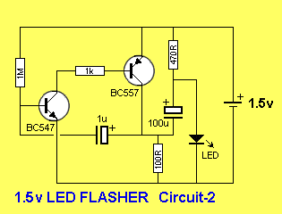
The 10u is now charged in the reverse direction and a negative voltage is presented to the base of the first transistor. This voltage is is gradually reduced by the electrolytic charging via the 100k and that's why the circuit has a very long off cycle.Two circuits are shown. They use slightly different components to produce the same results.
The only critical value is the 100R. The circuit will not work with a value higher than about 150R. It needs a low value so the BC557 transistor is turned on to a high level before a voltage is developed across the 100R. If the value is too high, a voltage will be developed across this resistor when the BC557 is turned on a small amount and this voltage will be sent to the BC547 to turn it on too. The two transistor will sit in a conditions that they are both turned on and the circuit will freeze.
The circuit has to function such that the BC547 is turned on to its maximum when the electrolytic is pulled HIGH. This transistor will now be turned on by the current delivered by the 100k (or 1M) plus the charging current of the electrolytic. As the electrolytic charges, the current into the base of the BC547 will fall and the transistor will turn off slightly. This slight turn-off must be passed to the BC557 to turn it off slightly too and lower the "turn-on" effect of the electrolytic. It is the 47R (or 100R) that is pulling the electrolytic down to the 0v rail and if this resistor does not have sufficient "pull-down" effect, the cycle will not continue. When this resistor has a low value, the BC557 must deliver a high current and it must be turned on via a proportionally high current into the base. This current comes from the BC547 and it needs a proportionally high current into its base to provide this condition. We are only talking about fractions of milliamps and microamps, but these conditions must be met for the circuit to work.


No comments:
Post a Comment