By simple, I mean that these circuits only flash one or two LEDs. This is opposed to the light chaser circuits that can flash four or more. Of course, the simplest LED flasher is simply to use a flashing LED. The problem with that approach is you have no control over the flash rate, but it does have its use for eye catching displays for selling stuff. The circuits below give you that control, plus they can flash two LEDs alternately.
There are many possible applications for the circuits below, especially for kids, who love flashing lights. Here's some possible uses.
-
Railroad crossing signal for model railroads.
-
Safety blinkers for bicycles, etc.
-
Fun stuff for Halloween, like making those plastic Jack-O-lanterns blink (try using ultraviolet LEDs here).
-
Christmas decorations.
-
Blinkers to locate items in the dark.
Transistor LED flasher
This circuit has a lot going for it. For one thing, it only consists of two transistors, two capacitors and four resistors. That also means it consumes very little power. You can control the flash rate by changing the size of the 100k resistors (100k makes for a pretty slow rate). You can also control the duty cycle by using resistors of different values on the two sides. The 470 ohm resistors control the current through the LEDs. Normally you want to limit this to 20mA, but to conserve battery power, you may need to limit it even further. You can also connect several LEDs in series, instead of using only one for each side. With red LEDs (1 per side) and the values shown, the circuit draws about 11mA. Here's what the actual circuit looks like:
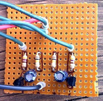
On this circuit, the green wires connect to the LEDs, but you can mount them on the actual circuit board for some applications. The picture is about twice actual size. Here is an example of the use of this circuit:

No comments:
Post a Comment