Here is a simple USB powered lamp that can be used to light your desktop during power failures. The circuit operates from the 5 V available from the USB port.The 5V from the USB port is passed through current limiting resistor R2 and transistor Q1. The base of transistor Q1 is grounded via R1 which provides a constant bias voltage for Q1 together with D2.The diode D1 prevents the reverse flow of current from battery.C1 is used as a noise filter.Two white LED’s are used here for the lamp, you can also use a 2 V torch bulb instead of LED’s. LED D3 indicates connection with USB port.
Circuit Diagram with Parts List.
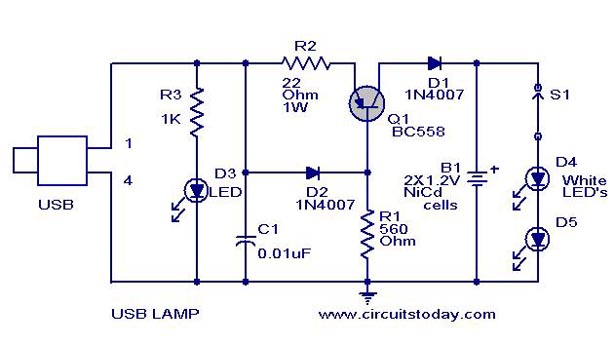
Notes.
- USB port is only able to provide up to 100 mA current.So don’t overload the circuit with more no of LED’s.
- Before wiring the circuit confirm the positive and ground leads of USB by a multimeter.
- Switch S1 can be used to turn on the lamp.
No comments:
Post a Comment